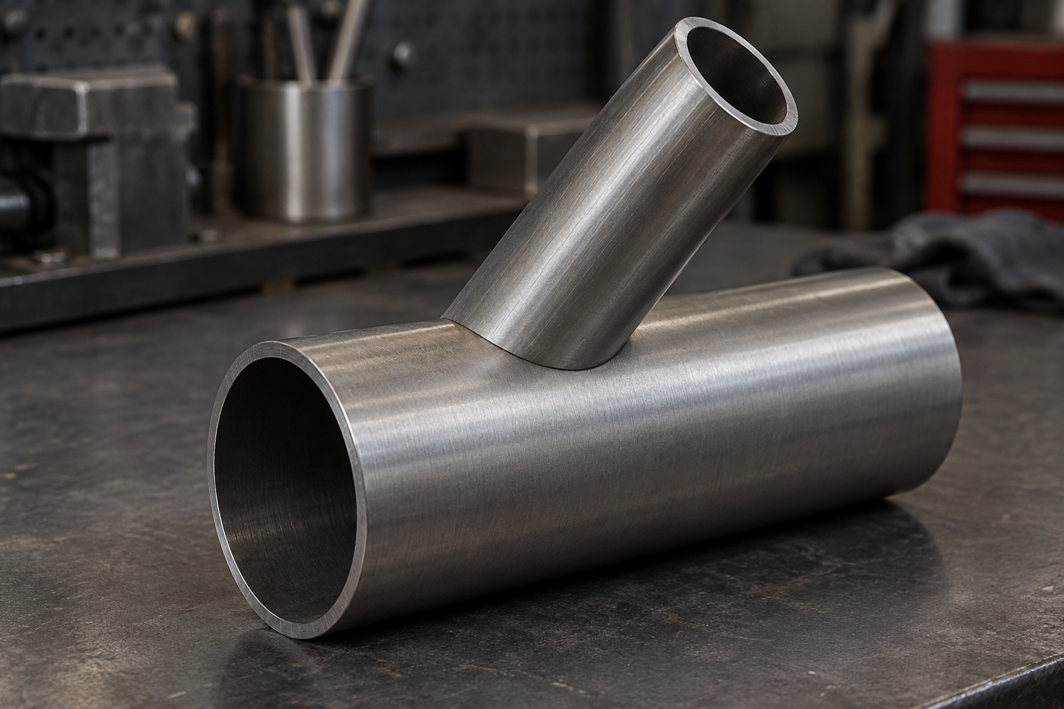
Set-on · 60°
Main OD 76 mm · branch OD 38 mm
Wall 2 mm → effective diameter 34 mm
 Pipe Cut TemplatesFeedback
Choose set-on or set-in, locate the center, and mark a closed opening on the main outer surface.
Choose how the branch meets the main.
Illustrative images, not fabrication dimensions.Load an example, inspect the joint, then replace its dimensions with your own.
Main OD 76 mm · branch OD 38 mm
Wall 2 mm → effective diameter 34 mm
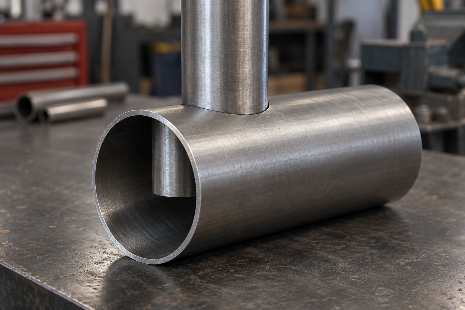
Main OD 76 mm · branch OD 38 mm
Diametral clearance 1 mm → effective diameter 39 mm
Effective opening diameter = branch OD − 2 × branch wall. This is a bore opening, not the branch-end notch.
Marking template only. Wall depth, bevels, weld gap and cutting direction are not compensated. For set-in joints, a radial cut through a thick wall may not clear the branch; finish the wall to the required fit.
Enter all three dimensions.
Loading saved opening…
Return to branch-end notching (set-on outer-surface profile)Start with how the branch will meet the main tube. The connection determines which diameter defines the opening.
The branch rests on the outside of the main tube. Enter its measured outside diameter and wall thickness to calculate the passage opening. Make the branch-end saddle separately.
Effective diameter = branch OD − 2 × wall thickness
Example: 38 mm OD and 2 mm wall → 34 mm effective diameter.
The branch passes into the main tube. Enter the branch outside diameter and total diametral clearance. Finish the main wall as required for the intended insertion and fit.
Effective diameter = branch OD + diametral clearance
Example: 38 mm OD and 1 mm diametral clearance → 39 mm effective diameter.
The effective diameter defines the intersecting cylinder, not the width of the unwrapped paper pattern. This tool calculates the main outer-surface outline; main-wall thickness, insertion depth and weld preparation require separate decisions.
| Parameter | Measurement reference |
|---|---|
| Main and branch OD | Measure the actual outside diameters. Nominal pipe size is not an outside-diameter measurement. |
| Included angle | Use the angle between the two tube centerlines: 90° is a perpendicular tee. Supported angles are 15–90°. |
| Wall or clearance | Set-on uses branch wall thickness. Set-in uses diametral clearance: 1 mm total gives 0.5 mm per side in the section normal to the branch axis. |
| Center from end | Choose a main-tube end and measure along its axis to the hole center. The near edge of the opening must stay on the tube. |
| Clock position | Look into the selected main-tube end. Use the end-view diagram to mark the clock position from the 0° reference. |
Enter OD, angle and the wall or clearance value. Confirm set-on versus set-in before marking any material.
Mark the axial distance and clock reference on the main tube. Check the appearance and measurement views, then review the flat opening.
Choose A4, Letter, A3 or Tabloid. Print at 100%, measure both calibration marks, and join tiled pages by matching both A/B targets.
Place the reference cross on the marked center and align the axial reference. Trace the closed solid loop; its inside is removed. Account for cutting and wall finishing in your fabrication process.
This page makes the closed opening in the main tube. A saddle or fishmouth template shapes the end of the branch tube. A set-on connection may need both templates.
The opening follows the intersection of curved cylindrical surfaces. Unwrapping the main tube changes how that boundary looks on paper; the angle and diameter ratio also affect the shape.
No. This is a local patch around the opening. Use its center cross and axial reference to position it on the main pipe.
Download the DXF for a closed 2D polyline in millimeters. HOLE_PROFILE contains the opening and REFERENCE_DO_NOT_CUT contains reference axes. Check the imported scale before using the geometry.
Yes. Solid lines identify the cut outline, dash-dot lines locate the opening, short dashed lines indicate paper trimming, and circled crosses align sheets. Verify the printed calibration marks before use.
Centered, straight round tubes with intersecting centerlines. The branch OD must not exceed the main OD, and the effective opening diameter must be smaller than the main OD. The tool checks dimensions and limits tiled PDFs to 64 pages. Offset joints, bevels, main-wall cutting paths and kerf compensation are not modeled.
This tool lays out a closed opening on the outside of a main, header, or run pipe, rather than a branch-end fishmouth. Choose set-on or set-in to generate a printable PDF, closed DXF profile, and marking information. Set-on uses the branch bore; set-in uses outside diameter plus diametral clearance.
Check the opening center, circumferential datum, and print scale on a test piece first. The model does not provide through-wall toolpaths, main-pipe inner-wall profiles, or structural reinforcement design.
Understand set-on and set-in · Position a printed main-pipe template · Need matching two-part templates? Open Joint tasks