
01. Check the printed scale
Check the file: use the main opening PDF and confirm the connection type, measured ODs, angle, wall thickness or diametral clearance. All sheets must share the same template code and paper size.
Print at Actual size / 100%. Disable Fit to page, shrinking and multiple pages per sheet. Match the PDF paper size to the printer, print single-sided, and do not tile the already-tiled PDF a second time.
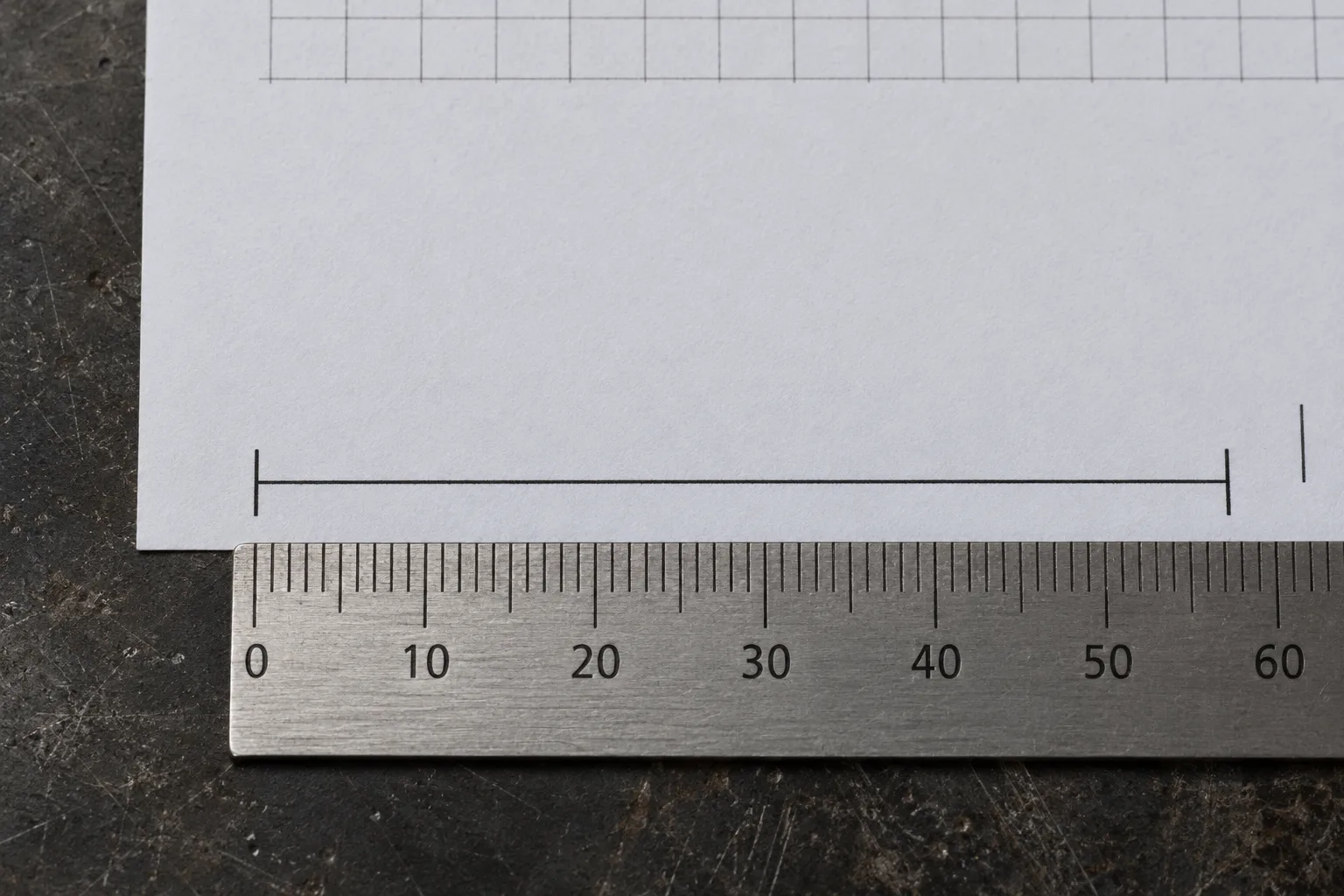
Measure the horizontal 100 mm and vertical 20 mm bars between their end ticks, using the ruler zero mark rather than its physical end. Verify every sheet you will use; measurements entered in inches do not change these check lengths.
If a 100 mm bar measures 97 mm, correct the print settings and reprint. Check both directions. Do not stretch the paper to compensate.
Completion check: both measured bars agree with their stated lengths to the accuracy your job requires. The calculator does not define the fabrication tolerance.
02. Trim, overlap and align the sheets
Arrange sheets by their large page numbers, rows and columns, left to right and then top to bottom. Skip joining for a single-sheet pattern. Keep the opening intact for now.
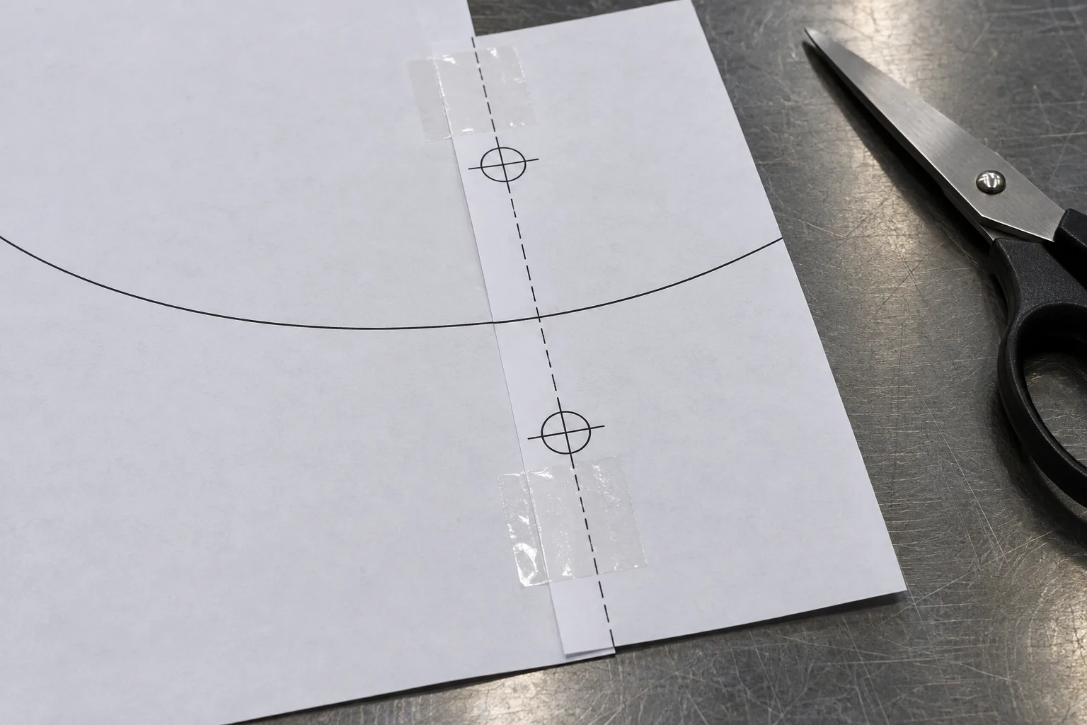
Where a left or top neighbor exists, trim that edge along the short dashed line through the registration-target centers. Do not trim every paper edge.
Lay the trimmed sheet over the preceding one. Match BOTH circled targets with the same page-pair and A/B labels, then tape. Matching only one point still allows the sheet to rotate.
Check that the cut curve and grid continue across the join. Keep tape clear of edges you need to trace. Do not butt paper edges together or add the overlap a second time.
Completion check: the strip outside the trim line repeats the neighboring sheet. Correct overlap preserves the whole profile; gaps or doubled curves mean you should realign.
03. Mark the center on the main tube
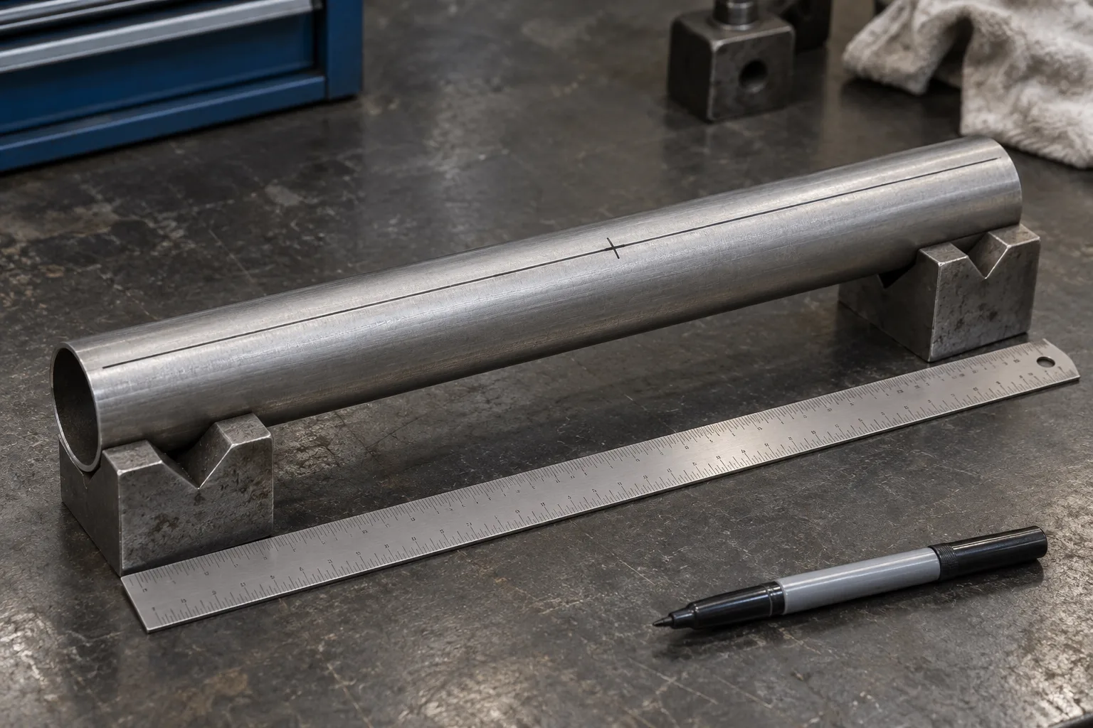
Support and secure the round tube against rolling. Remove oil and loose dirt so paper and tape can lie firmly on the surface.
Choose one main-tube end as the distance reference. Measure along the main axis to the specified hole center, not to the nearest edge of the opening or to the edge of the paper.
Draw a 0° reference generator. Looking into the selected end, measure clock position clockwise as shown in the end view. Circumferential arc distance equals main circumference × clock angle ÷ 360.
Mark the center cross and a short axial reference line. The hole center is where the branch axis meets the main outer surface. The template direction away from the selected end must match the intended branch lean.
Completion check: verify the selected end, center distance and clock position; make sure the entire opening stays on the available tube.
04. Position the patch and transfer the outline
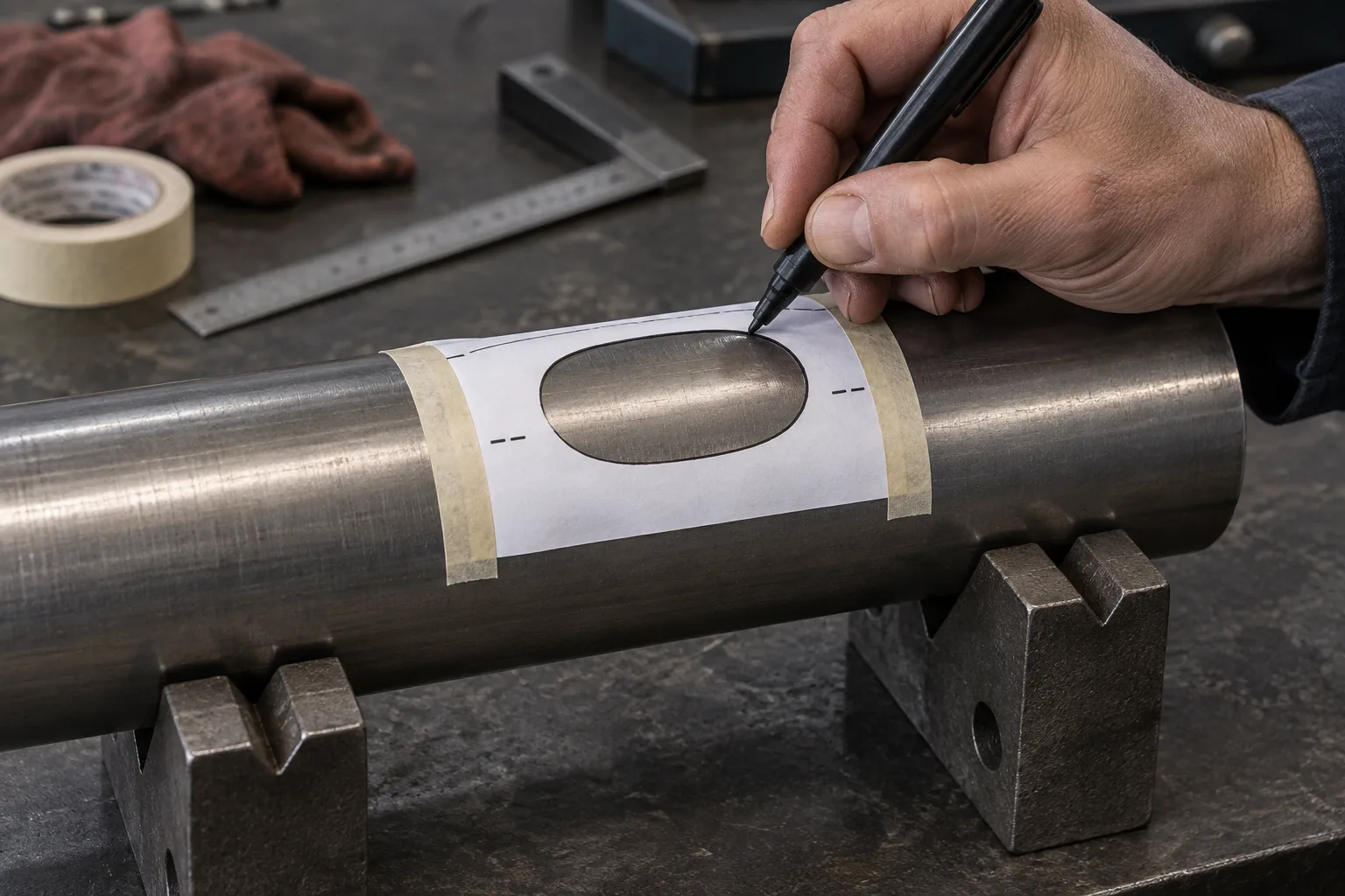
Position the complete template first: align its center cross with your mark and its axial dash-dot line with the main axis. Match the direction away from the selected end. This local patch need not wrap around the whole tube.
Smooth the paper over the cylinder without stretching it, then tape its margins. The tracing area must not bridge a gap, crease or bubble.
Option A: place transfer paper underneath and trace the closed solid outline with the template intact. Option B: transfer the center, axis and at least two external registration marks first; remove the template, cut out the closed opening, reposition it using the marks, then trace the window edge.
Remove the paper and inspect the metal line. It must be closed, continuous and correctly located. Remove material INSIDE the loop. Reference axes, paper trim lines and registration targets are not cut lines.
Completion check: if the window tears or cannot be relocated reliably, reprint or use transfer paper. Do not redraw missing portions by eye.
05. Cut and finish the opening
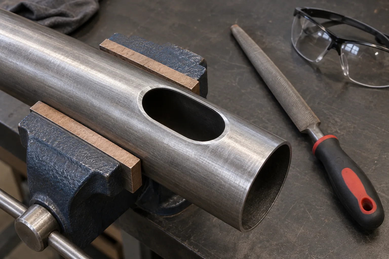
Recheck which material is removed. Remove paper and tape, clamp the work securely, and follow the chosen equipment instructions and protective measures. Select a process suitable for your material and wall thickness.
Do not assume that cutting along the center of the ink line produces the correct size. Kerf, cutting direction and finishing allowance depend on the fabrication process; the calculator does not compensate for them or prescribe a universal allowance.
Remove loose chips and burrs and finish local high points in small stages, preserving references for the final boundary. Do not enlarge the whole opening just to improve its appearance.
For a set-in joint, inspect the wall through the opening. A radial cut through a thick main wall may obstruct an angled branch even when the outside outline is correct. Identify the interference before removing more material.
Completion check: the part is ready for a dry fit. This guide does not determine bevels, welding procedures or pressure/structural suitability.
06. Dry fit and record the result
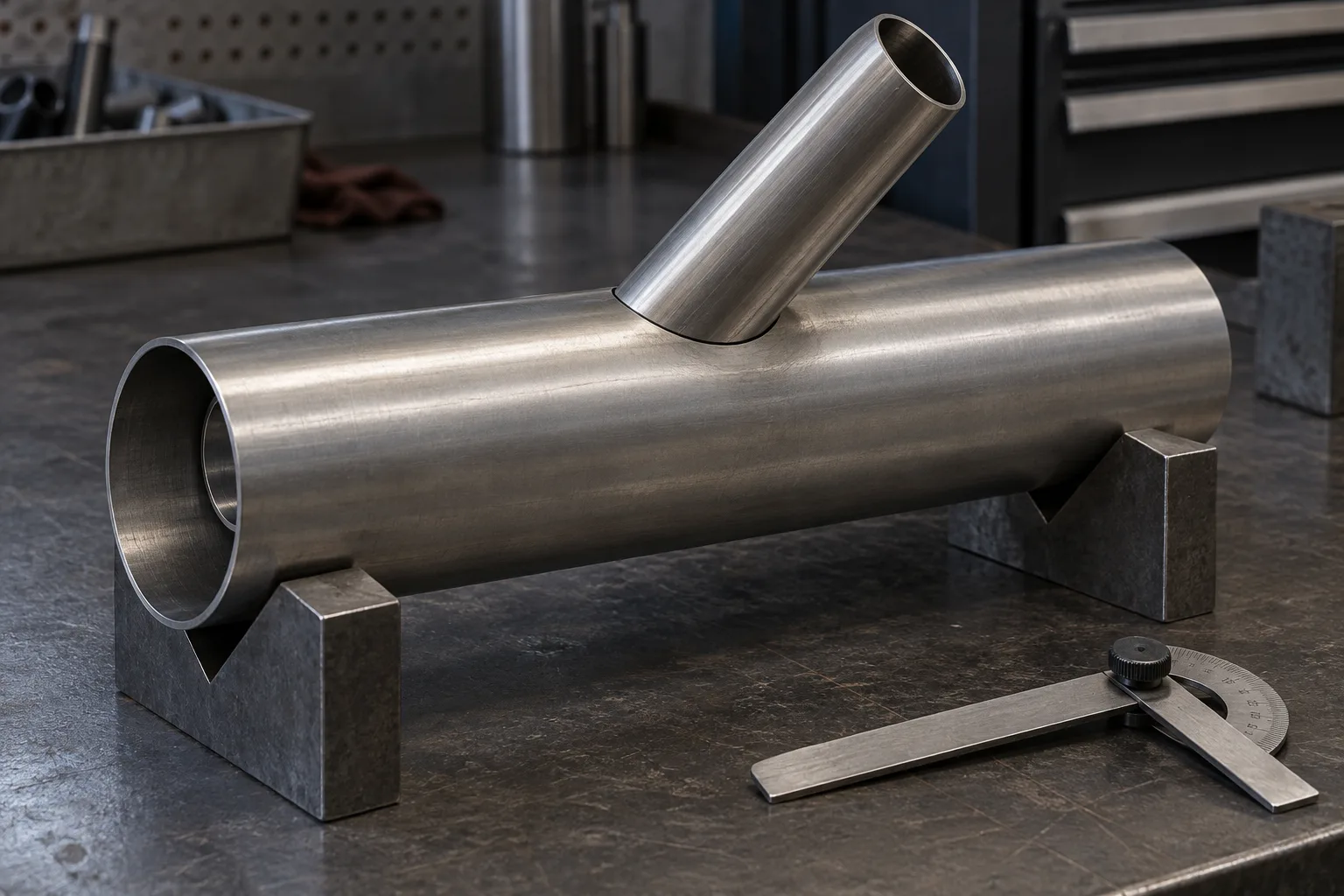
Use actual measuring tools to check center position, clock reference and the included centerline angle. Do not change the intended angle to force the branch into the opening or hammer it past interference.
Set-on: use the separate branch-end notch template so the branch end meets the main outer surface. Check the saddle fit and passage. The branch OD is not meant to pass through an opening calculated from the branch bore.
Set-in: trial-fit along the intended direction and check localized wall interference. Determine insertion depth from the job design. Diametral clearance is not a constant offset everywhere on the flat pattern.
Record dimensions, template code, paper, calibration readings, cutting/finishing method and fit observations. Confirm the process on a test piece before making repeated parts.
Completion check: an oversized opening cannot be restored by further grinding. Stop and reassess the dimensions, connection choice and process.
When the pattern or fit is wrong
Calibration bars too short or long: check scaling and paper settings in both directions. Do not stretch the paper or enlarge the opening to compensate.
Gaps or doubled lines at a join: check the template code, page order and both paired targets. Overlap the sheets instead of butting paper edges.
Curve outside the trim line: this is repeated content from the adjacent sheet. Correct overlap preserves the profile; do not add that strip to the finished pattern width.
Wrinkled paper or a lost center mark: transfer references before cutting a window. Reprint when reliable positioning is no longer possible.
Branch will not enter: verify set-in mode, measured OD, clearance, angle and local wall interference before enlarging anything.
A set-on main opening smaller than the branch OD is expected: it opens the bore while the branch stays outside. Its end notch is a separate pattern.
Keep the template code, dimensions, paper, horizontal/vertical calibration readings and fit notes with the job.